

Description
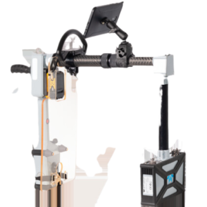
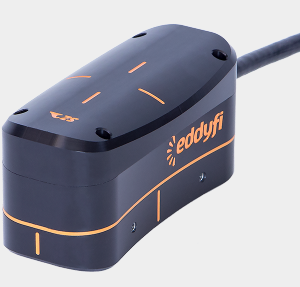
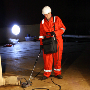
RMS2 is a high-speed, high-accuracy remote-access ultrasonic corrosion mapping system. It is designed to assess the condition storage tanks, pipelines, pressure vessels, and other critical equipment. It fits well in inspection programs supporting integrity management processes, ensuring effective and safe operation.
RMS2 offers 100% coverage in a band up to 1 m wide, significantly increasing the probability of detection (PoD) of defects, enabling engineers to determine optimal repair strategies, and improve remaining life assessment (RLA) and risk-based inspection (RBI) maintenance programs.
Flexible Solution
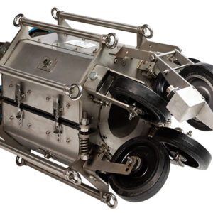
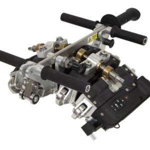
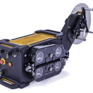
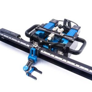
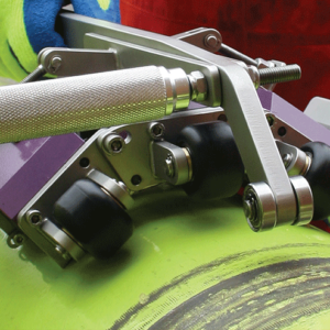
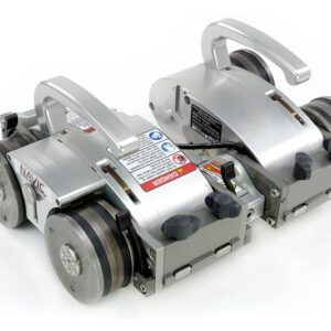
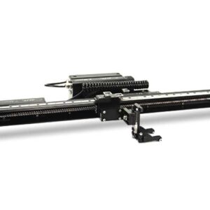
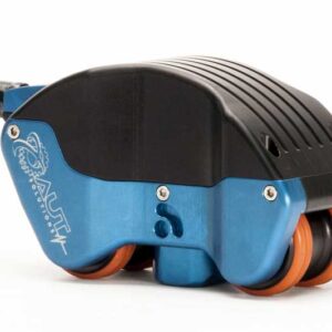
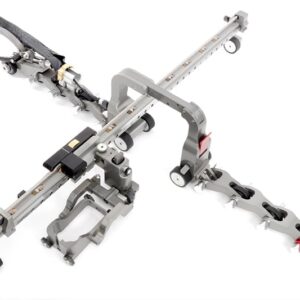
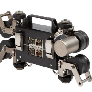
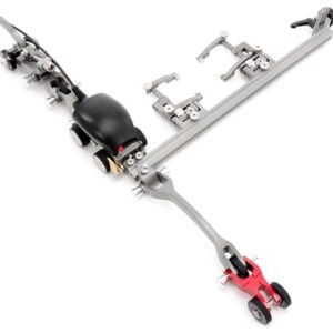
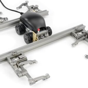
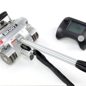
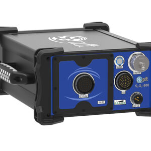
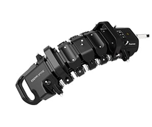
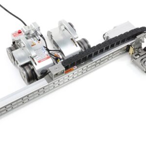
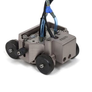
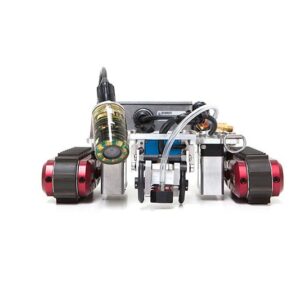
Every model in the RMS2 line, are equipped with automated ultrasonic scanner heads that share the same high-performance system controller, making it possible to use different heads according to inspection requirements. The steerable tractor of RMS2 incorporate high-torque stepper motors and powerful magnetic drive wheels, ensuring the scanner remains fixed to the inspection surface even when it is inverted.
Ultrasonic Scanners
RMS2-600
The RMS2-600 scanner head is designed to maximize scanning rates on large surfaces such as tank shells, pressure vessels, and other structures.
- 600 mm (23.6 in) scan bridge
- Designed to inspect large surfaces
- Storage tank shells, horizontal tanks, pressure vessels, spheres, ship hulls, large structures
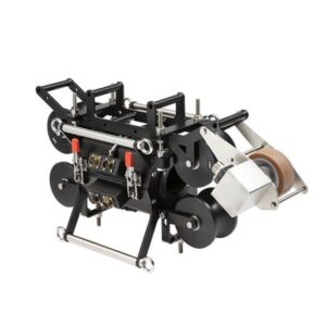
RMS2-450
The RMS2-450 scanner head is designed for circumferential operation on curved surfaces from 152 mm (6 in) in diameter to flat surfaces.
- 450 mm (17.7 in) scan bridge
- Designed to inspect the circumference of curved surfaces
- Pipelines, pressure vessels, horizontal tanks, other structures where circumferential inspection is necessary
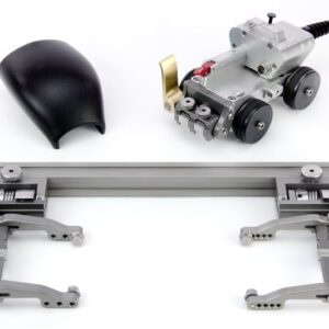
RMS2-300
The RMS2-300 scanner head is a general-purpose scanner to inspect areas with limited access or other applications where smaller scan widths are necessary.
- 300 mm (11.8 in) scan bridge
- Designed to inspect limited-access areas
- Storage tank shells, horizontal storage tanks, pressure vessels , spheres, ship hulls, large structures
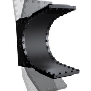
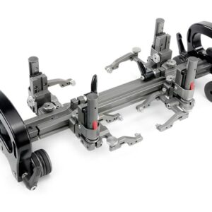
RMS2-ARC
The RMS-ARC 24 -36 and 36-48 are designed to operate longitudinally on pipes 610–1219 mm (24–48 in) in diameter. The combination of longitudinal pipe scans and 60° width is a major improvement to ultrasonic testing (UT) efficiency in pipeline applications, while maintaining the high data quality associated for which RMS2 is known for.
- Up to 1 m (3.3 ft) scan bridge
- Designed to inspect pipe 610–1219 mm (24–48 in) in diameter longitudinally
- Pipelines, slug catchers
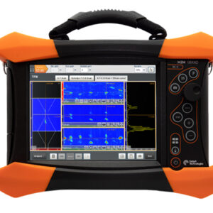
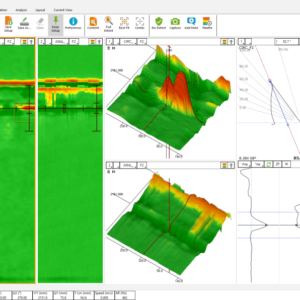
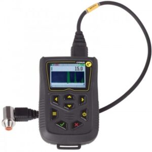
Data Acquisition Software
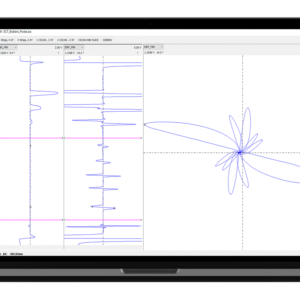
The RMS2 software integrates scanner control, data capture, data analysis, and reporting tools. The software displays ultrasonic A-scan, C-scan, thickness measurements, and positional data in real time, with a maximum resolution of 0.5 × 0.5 mm (0.02 × 0.02 in). This information is recorded when a scan is saved. The modular user interface is designed to hide and restore infrequently used controls with a single click, and save specific display layouts for future use. The ultrasonic controls are similar to those on a standard ultrasonic flaw detector, therefore trained ultrasonic operators can quickly become familiar with all the software functions.
C-Scan Layers and A-Scan Gates
The RMS2 software is designed around the concept of C-scan layers, which enables operators to quickly switch between the multiple C-scan views generated during scans. The A-scan trace and the C-scan image are displayed in real time, and you can add multiple A-scan gates to measure between portions of the trace. This means you can measure the signal’s amplitude, the part thickness, the internal surface profile, and the external surface profile simultaneously. After acquiring the scan, you can analyze it again by adjusting gate settings to produce a more accurate C-scan image or highlight particular indications. This powerful tool minimizes the need for re-scans caused by changes in surface conditions or minor setup errors.
A-Scan Processing and Floating Gates
RMS A-scan waveform processing is completely digital, in real time during scans and during post-processing. The system records A-scans in raw unfiltered RF form, which can be processed afterwards, including rectification, filtering, wave smoothing, and noise rejection. This minimizes the setup on site and avoids re-scans caused by incorrect ultrasonic setups. Another feature of the RMS2 software is floating flank gates. The floating gates track to the same percentage of the signal amplitude. This enables signals of much lower amplitude to be picked up, improving the accuracy and increasing the efficiently of data analysis and reporting for greater confidence in inspections.
Ultrasonic B-Scan Amplitude View
The amplitude view shows the B-scan profile in both X and Y dimensions at a selected point in a C-scan. Using the B-scan amplitude view, operators can easily identify any defects or inclusions. C-scans are an effective method of viewing general wall thinning and larger defects, but small pit and inclusion indications can often be difficult to see because of their small surface areas. By reviewing acquisitions in B-scan mode, you can quickly identify and size these potentially critical indications. The software also has a stacked B-scan mode to help with identification of step-wise cracking and defects not aligned with the X and Y scanning directions.
Features
- Automated/Remote-access UT scanner
- High-speed ultrasonic testing
- High probability of corrosion detection with up to 0.5 mm (0.02 in) scan grid
- Import inspection data to CMAP
- Range of scanning heads
- Inspection confidence
- Field-proven durability and reliability
- Helps reduce maintenance costs by minimizing use of scaffolding
- No paint removal required
- Real-time image display
- Wide range of applications up to 200 ˚C (392 ˚F)
- Inspect materials as thick as 150 mm (5.9 in)
- 3D data view for internal/external profiles
- Can be used on any ferrous item from 152.4 mm (6in) NB to flat plates
- Longitudinal scanning head for increased productivity on crude oil transfer lines, slug catchers, and the like
- Up to 50 m (164 ft) long × 1 m (3.3 ft) wide scan data acquisitions, feasible in one location
Specification
ULTRASONIC TECHNICAL SPECIFICATION
Pulse voltage
40 to 300
Pulse width
50 ns to 530 ns
Damping
500Ω
Receiver gain
-20 db to 80 db
Bandwidth
0 MHz to 25 MHz
Waveform
Full rectified, + half rectified, – half rectified or RF
Range
4.8m in steel with velocity 5920 m/s
Transmitter mode
Single, dual
Transducer range
2.5 to 10 MHz
Reject
Baseline compression
Post trigger delay
0 to 3.2 ms, 20ns step
TRANSDUCER SPECIFICATION
Standard Transducer Specification
5 MHz 50 mm focus
6 – 12.5 mm, (0.25 to 0.5 in)
5 MHz 75 mm focus
12.5 – 50 mm (0.5 to 2 in)
Optional Transducer Specification
10 MHz 40 mm focus
1 – 6 mm, ( 0.04 to 0.25 in)
2.5 MHz non-focused
50 – 150 mm (2 to 6 in)
5 MHz dual
2 – 100 mm (0.08 to 4 in), requires an adapter
Others available on request
Transducer Holder Range
Standard Maximum thickness
100 mm (4 in)
Extended Maximum thickness
280 mm (11 in)
COMMON SCANNER SPECIFICATION
Scan grid
0.5 to 150 mm in 1 mm steps (0.02” to 6”) independent X and Y
Maximum scan length
60 m (200 ft) at 10 mm (0.4”) grid
Maximum scan speed
730 mm/s
Auto – position
Scanner movement to origin or selected point
Scanner identification
Automatic
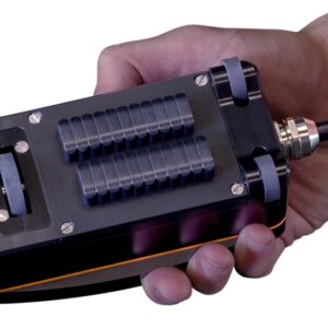
Scanner control
Joystick controller and software
Umbilical cable
15 metre (optional 30 metre)
Temperature range
Up to 200°C
Power requirements
100 to 240 VAC – 50-60Hz